A while ago I noticed that Eddy OE3SEU was sending APRS position data from his trip in ZS and V5. Shortly after that I discovered that this was done using Robust Packet via geostationary satellite QO-100 where he was also QRV on in SSB. So this was a nice source of information which grid locators he will be active from and when (very roughly). As I was planning a trip to OZ and SM later this year I took into acount using the same for beaconing some APRS data.
Mike OE3MZC is running an experimental APRS iGate listening on the downlink frequency 10,489.581 MHz USB in RPR300 and FSK300 packet radio. Received beacon info is then gated to the APRS-IS on the internet. Besides some Windows-only software solution there is the SCS Tracker DSP TNC that you can use as modem. I could get hold of one of these (as they are EOL since 2020).
The unit has a standalone tracker mode which can use a GPS unit to read position data from. My junk box provided an ublox NEO-6m GPS module in a plastic case which has not been used for years. Regarding the GPS connector the manual of the SCS tracker states:
This input is compatible with 5V-TTL and RS232/V24 signal levels. The GPS output is TTL Level.
So I figured I can directly connect the GPS module. My (newer) unit also provides a +5V pin so that no extra wire is needed for powering the GPS unit. So I did … and waited for the SCS Tracker to read position data.
But nothing happened. The PWR/NMEA LED was flashing red and green which indicates that GPS position data is invalid. So I spent an afternoon debugging and even connecting a Beitian BN-880Q GPS unit from my parts box which showed the same result. Even after an hour it would still say that position data is not valid.
Then suddenly an idea popped up. The logical levels of ones and zeros are inverted when it comes to comparing TTL and RS232. For TTL a logic high is represented by Vcc (5V) and logic low is 0V. For RS232 it is the other way round: Logic high is represented by negative voltage (-13V) whereas logic low is represented by positive voltage (+13V). Thus the manual of the SCS Tracker is a little unspecific here. Just because it says that the port can cope with TTL and RS232 levels it does not mean that it would be able to apply the needed inversion when using TTL instead of RS232 logics. Damn it - this has cost me almost a day to find out…
So then it was time to design a small inverter circuit. This can easily be achieved with a NPN transistor and two resistors:
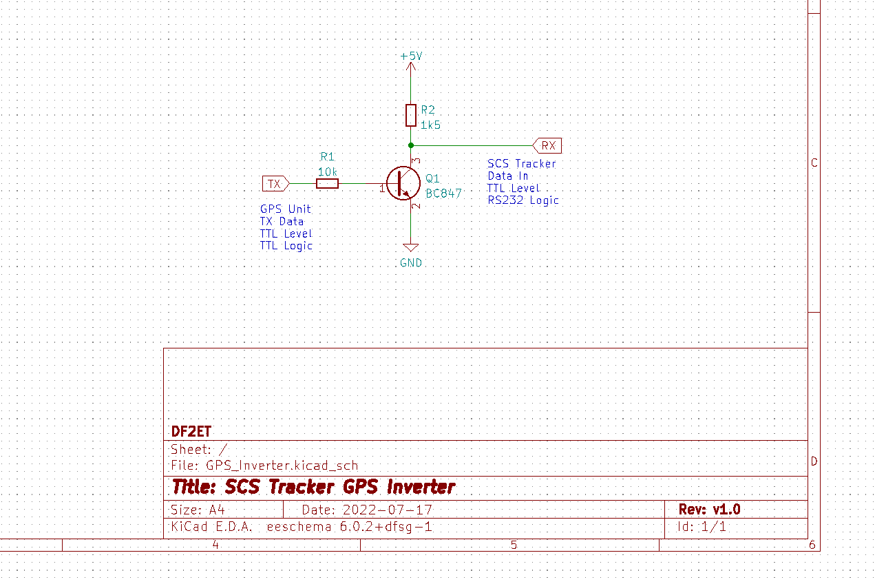
And the result should follow almost instantly. After inserting the parts the SCS Tracker would read the GPS information from the TTL GPS unit after some time of synchronizing. If the manual would have given a hint I had saved a day for some more QSOs. :)
As my GPS unit is boxed in a little plasic case I decided to use some spare 0603 and 0804 SMD parts for the circuit. This way the circuit has been added inside the case rather than having some external parts floating around.
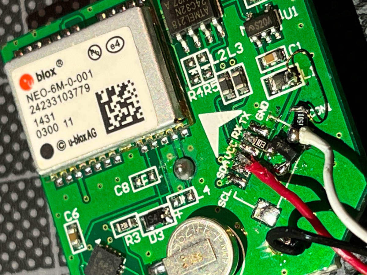
The original connector was desoldered. Instead I connected the +5V wire (red) to the corresponding pad directly. For GND (black) I scraped off some paint from the PCB and this was also done for connecting the emitter of Q1 (BC847) to GND. The original TX pin (labels are off by one) is connected to the base of Q1 via a 10k resistor. And the pull-up resistor (1k5) is hooked up to +5V on the right pad of L1. Between R2 and the collector of Q1 the output wire (white) to the SCS Tracker is connected.
I hope that this may save others some time while debugging why the SCS Tracker would not cooperate with a TTL-level GPS unit although the manual gives the impression it would out of the box.