With the integration of POCSAG/DAPNET features into the MMDVM/MMDVMHost I came to think about if it would be possible to combine an MMDVM repeater/HotSpot with a DAPNET tranmitter. The advantage in Germany is that there is a single coordinated frequency for POCSAG tranmissions on UHF. 439.9875MHz is used for fixed-frequency pagers which are modified to receive on that frequency. With latest hand-programmable pagers (e.g. AlphaPoc) it would basically be possible to set them to the repeater frequency but that wouldn’t work while one is en route.
In the programming software for Motorola GM3x0 radios I found an interesting GPIO setting called “Channel Steering”. Some line of the help function revealed that it would exactly do what I expected. You can trigger a GPIO and the radio switches channels.
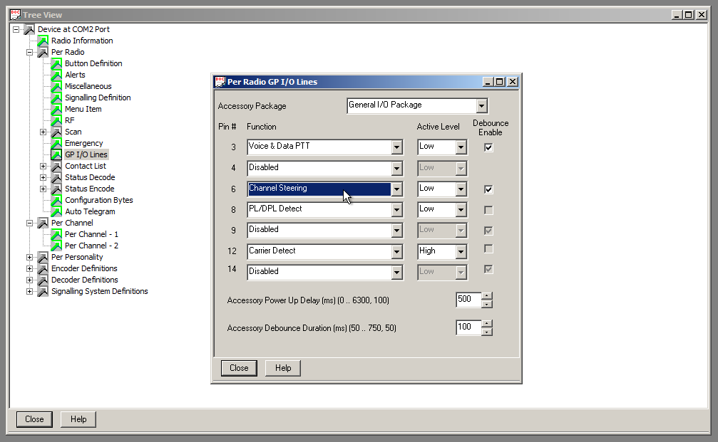
The basic idea is to use a MOSFET transitor to pull the GPIO pin to GND (active low) while in POCSAG mode. The MMDVM firmware basically supports this and is currently extended to have the support also for the F7 based MMDVMs. It was originally designed to switch antennas or filters so exactly suits my needs here. As can be seen on the picture I configured GPIO 6 as “Channel Steering” and active low. This GPIO is routed to pin number 6 on the ACC connector at the back.
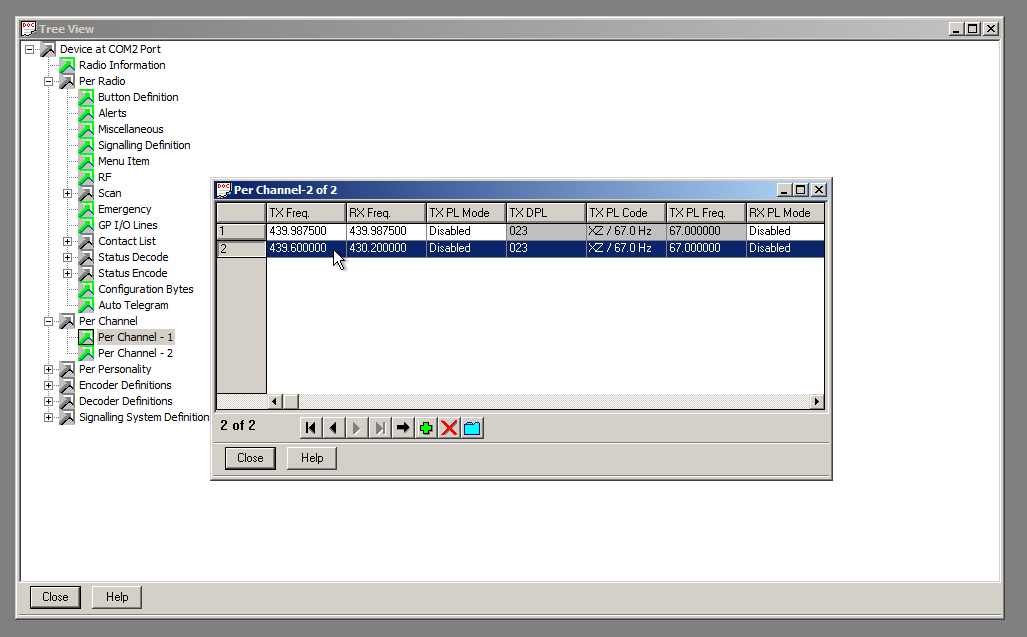
As I only use on GPIO I can switch between two channels. For my demo I configured my HotSpot frequency as well as 439.9875MHz which my Skyper (NEC21a) is working on. Interestingly pulling the GPIO low switches to channel 1. So I set my HotSpot QRG to channel 2 and the POCSAG QRG to channel 1.
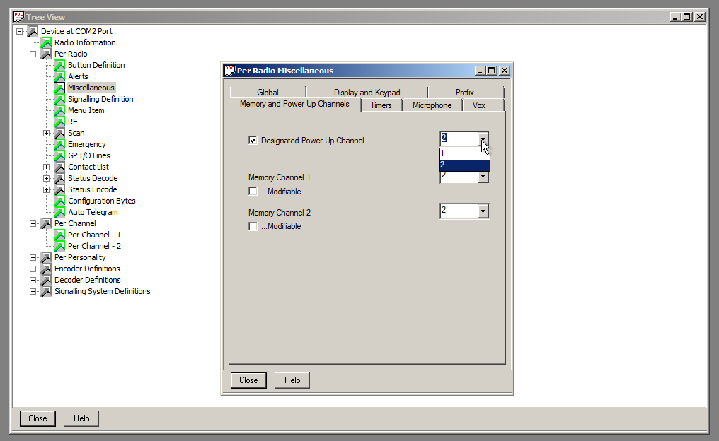
And in order to make sure that the radio always comes up with channel 2 I configured the so-called Designated Power Up Channel to be channel 2. This can be found in the miscellaneous settings of the radio.
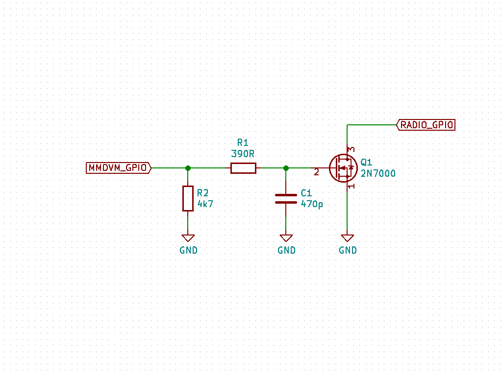
So what is left is the connection to the MMDVM. I used a 2N7000 MOSFET with a series resistor of 390Ω, a pull-down resistor of 4k7Ω and a 470pF capacitor. The schematic is shown in the following picture:
As a quick hack I reconfigured the NXDN LED of my F4M board by Toufik F0DEI to be the extra GPIO for channel switching for POCSAG transmissions. So as soon as there is a POCSAG telegram to be sent this trigers the GPIO and lets the radio switch to 439.9875MHz. And after that is done the GPIO is de-asserted and the radio switches back to the HotSpot QRG ready for any other DV mode. Expect the MMDVM code [1] to be updated the next few days to support an extra GPIO for this purpose.
This is a quick video demonstrating the purpose:
{% youtube TbZAUP–kPs %}