A while a ago the modification for an Opticum Quattro LRP 04H LNB was documented. Recently there was need to rework another one for similar purposes. This time the DC parts for the low LO outputs were to remove. The case looked a bit different and the interior obviously contained a completely different PCB design.
The main difficulty was that the outputs where not clearly labelled so it was hard to identify which were the high and which the low LO ports. This was solved experimentally by wiring the LNB up and testing against CW beacon on QO-100.

In contrast to the previous version of the LNB the outputs are in different order. From the view in the picture the ports are as follows:
- Number 1 (leftmost): Low LO / vertical polarization
- Number 1 (2nd from left): High LO / vertical polarization
- Number 1 (2nd from right): High LO / horizontal polarization
- Number 4 (rightmost): Low LO / horizontal polarization
The original case has the following labels on the bottom (which were extend with some painted arrows):

So the leftmost port would be used for QO-100 narrowband part of the transponder and the rightmost for wideband part. So the last part was to remove the two diodes from the DC part for low LO V/H outputs. Those were easy to identify and shown in the following pictures.
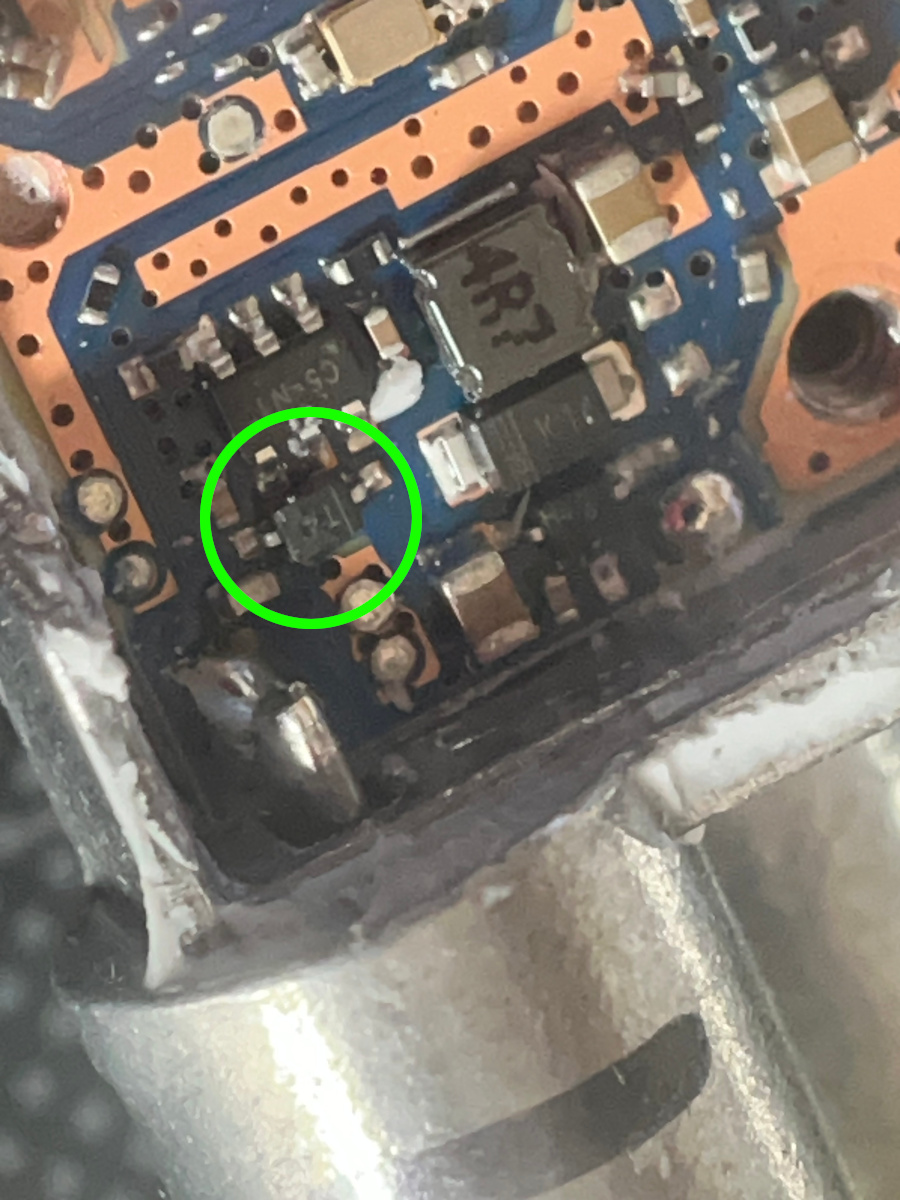
Diode to remove for the vertical output:
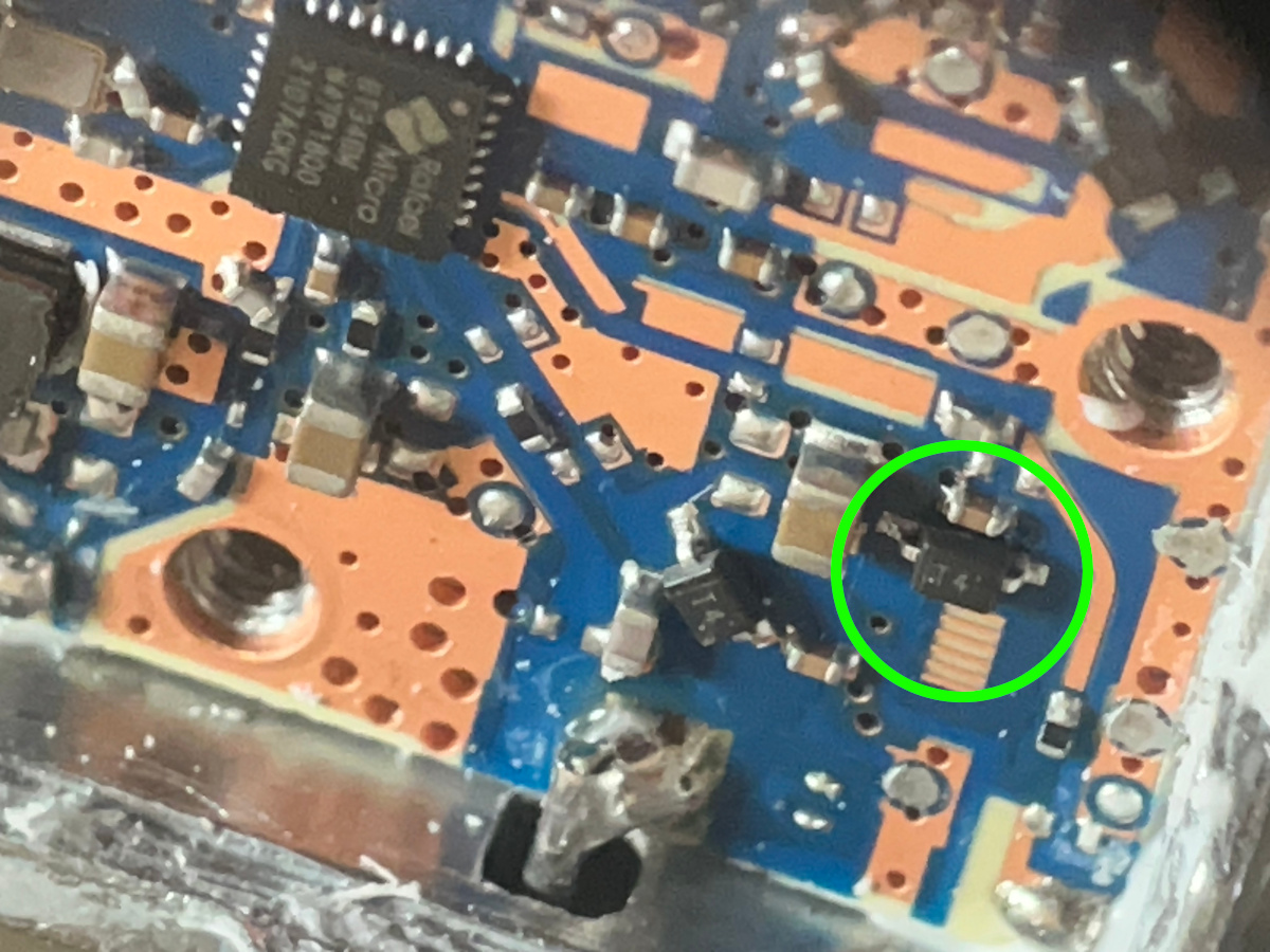
Diode to remove for the horizontal output:
After this modification the LNB still runs with the built-in crystal (i.e. not stabilized) and it can be powered by 12V on one of the two middle ports. No bias-T and no 18V for horizontal output is needed. The RX / down converter can be connected to the outputs directly.